Thermofluid calculation models
Software-based analysis of pipeline pressure drop, heat-exchanger energy balance, and a vacuum system’s energy demand, with assumptions & sensitivity curves.
What I did
- Set out the inputs, units, equations and sensitivity tables in Excel for a pipeline, a heat exchanger and a vacuum system, and documented the assumptions behind each model.
- Used Goal Seek for the pipeline flow, Solver for the heat-exchanger flow rates and outlet temperatures, and the analytical isothermal work equation for the vacuum system.
- Ran sensitivity cases: pipeline and heat-exchanger flow rates, and the vacuum system’s target pressure against pressure ratio, work and power demand.
- Rebuilt the three models in JavaScript for this page, so each operating point can be explored live against the assessment values.
Pipeline pressure drop
A 100 m long, 0.5 m wide pipeline carries oil at 0.1 m³/s. The Darcy–Weisbach equation with the laminar friction factor was used to find how much pressure is lost to wall friction along the pipe at varied flow rates.
- Reynolds number
- 2165 (laminar)
- Pressure drop
- 651.9 Pa
- Head loss
- 0.0783 m
● Current □ Assessment
Heat exchanger
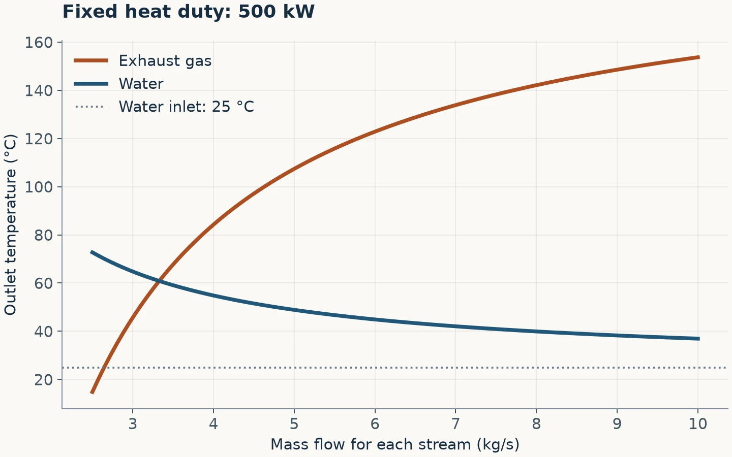
A process needs 500 kW recovered from hot exhaust gas into water, cooling the gas and warming the water without the two streams mixing. Each stream follows the steady-flow energy balance Q̇ = ṁcₚΔT at the fixed duty.
- Water outlet temperature
- 50.09 °C
- Gas outlet temperature
- 69.99 °C
Water · Gas — outlet temperature versus mass flow
● Current □ Assessment
Vacuum system
A 1 m³ chamber has to be pumped down from atmosphere to 0.01 atm (1.013 kPa) and held there for a manufacturing process. The model gives the theoretical minimum energy to evacuate it and shows the energy climbs steeply as the target pressure falls, so specifying no deeper a vacuum than the process needs is the biggest energy saving available.
- Pressure ratio
- 100 : 1
- Isothermal work
- 466.5 kJ
● Current □ Assessment